Mach3 Troubleshooting

This week I spent some time with my aunt and uncle. My uncle is a mechanical genius and a visit to their property is always enjoyable. This trip was no different, me being led on the obligatory workshop tour as my uncle filled me in on the status of his various car restorations, instrument making projects and machine tool acquisitions.

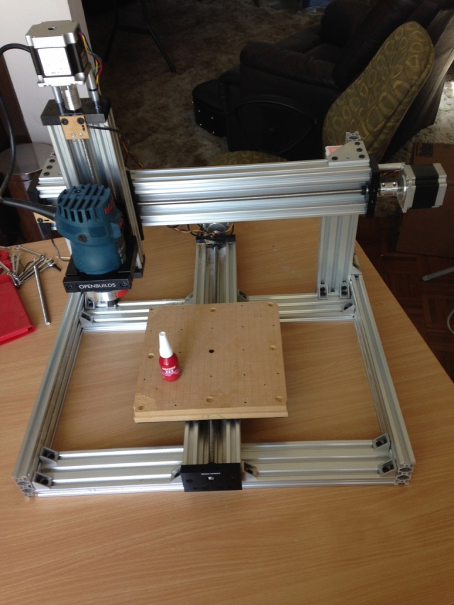
This trip was a little different, this time I was able to make a contribution to one of his projects. Some time ago he had purchased a Chinese 6040 CNC mill on eBay:

bdcc14a2-f89d-423d-be6c-9d70c5a44f99

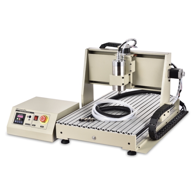
Unfortunately he hadn’t been able to get it going and it had been sitting idle. It had been supplied with Mach3 v2.58 but whilst the software installed ok and the controller powered up, the only thing it would do is power the stepper motors and ‘hold’. No amount of jogging or config change would make it step.

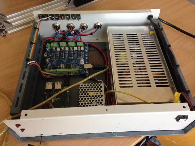
The CNC controller is generic Chinese, the beige one with a sloping front panel, variable frequency drive (VFD) controller, 4 channels (X, Y, Z and A) plus an emergency stop. It connects to the PC via a parallel cable. After taking off the cover I found a TX14175 parallel breakout board (BOB) and four stepper motor drivers, model TX14207. The VFD front panel was marked PRT-E750.

Poking around the PC’s parallel port with a multimeter I was able to measure 3.3 volts on many of the outputs, pins 1-9, with the ground connected to pin 25. According to the mill documentation pin 14 was meant to be an ENABLE signal but clicking the RESET button in mach3 made no difference to the voltage level on the pin.

Software Changes

The PC was running Windows 7 64-bit. According to the Mach3 requirements page this won’t work. It needs to be the 32-bit version so an operating system downgrade was performed and Mach3 v2.58 re-installed. After some minor reconfiguration and testing I was still unable to get Mach3 to toggle the parallel port pins.

At this point I took another look at the Mach3 downloads page. The current version is 3.043, a little more up to date than the version I had disks for. During installation of the latest version I encountered my first bit of luck, the system asked me if I wanted to install a parallel port driver. With the parallel port driver installed and the newer Mach3 configured I was able to get the multimeter needle to move.

Stepper Motor Configuration

The next stage was to connect the parallel cable and power up the controller. I decided to track down the emergency stop input by using the diagnostics screen and the ports and pins config page. A bit of trial and error identified the signal coming in on pin 10. I immediately got a warning about an external condition. Changing the input to active low fixed the problem and I could happily push the E-Stop and see the Emergency indicator light in the diagnostics panel.

I configured the enable pin next. From memory this was on pin 14 and was active low (I am no longer at my uncles place).

Stepper motor config was X (2,3), Y (4,5), Z (6,7) and A (8,9) – (step,dir). Once these were entered I was able to move the machine around. A little fiddling with the motor config and a ruler determined that there were 400 pulses to the mm. The pulse/mm setting is dependent on 3 things, the stepper motor (200 steps/rev), the ball screw (4mm/rev) and the drivers micro step setting (x8).

Other motor settings I played with were the maximum travel rate, 1200mm/min for X and Y, 400mm/min for Z and the max acceleration of 8mm/s^2. This was something I didn’t spend much time experimenting with. It seemed much improved over the default values without missing steps during movement.

NB. All step and dir pins are on port 1.

Spindle Configuration

This is the area that was hardest to nut out. From the information I had to hand there are two signals from the PC that are used to control the spindle. Pin 17 turns a motor relay on and off and pin 1 has a pulse width modulated (PWM) signal used to control the spindle speed.

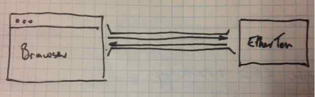
The breakout board outputs two signals to the VFD. One is a simple digital (on/off) signal that is connected to the VFD Fwd input. This makes the spindle spin clockwise. The second output is an analog control voltage and is used to control the speed. The VFD is capable of spinning the motor in reverse but as supplied the CNC controller had not provided that capability i.e. the Rev input was disconnected.

You can operate the spindle manually using a front panel knob to control the speed. At minimum the display showed 0 and at maximum 400. This is the drive frequency in Hertz so it needs to be multiplied by 60 to get RPM. Maximum speed for my uncles spindle was 24,000RPM.

I found the public forum information on Mach3 spindle configuration to be poor and often misleading. The Mach3 manual gives a better understanding but no examples. You have to read several sections and then synthesise to get the complete picture.

For the TX14175/PRT-E750 combo I found that I needed to specify:

  1. Motor Outputs – Spindle – step on pin 1, active low (dir is unused)
  2. Output Signals – Output #1 – pin 17, probably active low
  3. Spindle Setup – Disable Spindle Relays – unchecked
  4. Spindle Setup – Clockwise (M3) Output # – 1, probably active low
  5. Spindle Setup – CCW (M4) Output # – 2 (dummy value)
  6. Spindle Setup – Use Spindle Motor Output – checked
  7. Spindle Setup – PWM Control – checked
  8. Spindle Setup – PWMBase Freq. – 5
  9. Spindle Setup – Minimum PWM – 0%
  10. Spindle Pulleys – Pulley # 1 – min 0, max 24000, ratio 1

It is important to bear in mind that Mach3 is processing Gcode to control the CNC hardware. A typical gcode block would be “S1000 M3” to make the spindle spin clockwise at 1000 RPM. Let’s walk through the above settings to determine the effects.

When Mach3 encounters an M3 code it will activate Output #1 (point 4) which is wired to pin 17 (point 2). This will turn the spindle on. It should also effect the VFD freq display – it flashes when off and is solidly lit when on. This is one way to work out the active low/high setting. If it stays solid when M5 is issued you have it the wrong way around i.e. motor on when it should be off.

When Mach3 encounters an M4 code it will deactivate Output #1 and activate Output #2 (point 5). As there is no output signal configured for this output nothing happens. The VFD display should flash.

Spindle speed involves generating an analog voltage from a PWM signal (google it). Mach3 needs to know the min/max spindle speeds which it gets from the pulley setting (point 10), 24,000 RPM. Using the speed from the example above, S1000, the PWM signal needs to be roughly 4% (1000/24000). This is output on pin 1 due to the settings in points 7, 6 and 1.

One thing I found when experimenting with the spindle speed was the effect of getting the active high/low setting for the spindle output wrong. If you find the spindle spinning fast at low values, e.g. S1000, but slow at high values, e.g. S24000, then this needs to be inverted.

Summary

This is by no means a complete configuration for a Chinese 6040 mill controlled by Mach3 but it should get you started.

Go make some chips 😉


Posted in CNC | Tagged , , , , , , , , , , | 2 Comments

CNC Mill – First Cuts

In January 2018 my Openbuilds C-Beam mill became operational. It’s now early February and I thought I’d post on what I’ve learned in the last four weeks.

This is what the finished product ended up looking like:

IMG_0310

Hardware

The mill itself is based on the Openbuilds C-Beam plate maker design. I ordered the parts from Maker Store in Victoria. The extrusions I ordered in 1000mm and 1500mm lengths and cut to size myself. I did make one modification to the standard design, the original plate machine was 250mm high. I made mine 300mm, in the hope that I would be able to get better clearance. This is probably a mistake and will require future correction.

The standard spindle bracket has a 72mm hole. In the USA this fits the Bosch Colt router. In Australia the equivalent is the Bosch GMR 1 Professional. I considered using either the Makita or DeWalt but both have 65mm barrels and require some sort of adapter make them fit the bracket. This may be something I want to do in future, especially now that I have the ability to machine one out of acrylic.

The Bosch router had some issues with the collet. It was supposed to be 6mm but would not tighten up sufficiently to hold any 6mm bits. I tried 1/4″ but these wouldn’t fit, too tight. Bosch Australia were unhelpful. My patience wore thin and I eventually bought after market collets from Elaire Corp. Am very happy with the Elaire products.

Stepper motor control is handled by a Syntheos TinyG v8. The mill uses NEMA 23 steppers, some of which are at the upper end of the TinyG’s power capability. I have experienced no issues due to thermal overload. The mill has run comfortably in my shed on hot summer days where the temperature was around the 40C mark. I run the board without any cooling:

IMG_0313

The other board in the photo is a Beaglebone Green (bottom left). Right now it is not being used due to RFI problems with the WiFi. I suspect the spindle motor is blowing it off the air.

I am using my laptop to control the machine using the USB cable visible on the left.

Software

The TinyG works well with Chilipeppr, an open source control system that runs in a browser. Chilipeppr is feature rich and offers several ‘niche’ control specialities, PCB milling for example.

I tried using LibreCAD for drawing. It worked well for the drawing part and I really liked the way you could enter shape details via keyboard. Other CAD packages rely heavily on the mouse, something I find awkward.

A Ben Heck video I saw on YouTube made the case for a toolset based on Inkscape (SVG) passing on to JsCut, a browser based GCode/toolpath editor. Tried using Inkscape on Mac and found 1) it’s extremely powerful (big learning curve) and 2) not Mac native (uses XWindows). JsCut is very particular about the SVG structure; requiring SVG paths instead of objects. When combined I found this toolchain to be ‘clunky’. Inkscape is a graphic designers tool, not really a CAD package. My application right now is machining small components out of MDF/acrylic and aluminium.

I finally settled on CamBam. Admittedly it is not free software but it appears to get the right balance between CAD/CAM input and usability. Right now I am part way through their trial period. You get to launch it 40 times for free, after that you have to pay.

With CamBam you edit two separate models, the drawing and the operations. You start out by drawing a plan view of the thing you want to make (i.e. CAD). Once you have drawn the shape outlines you apply machining operations like drill, pocket and profile to generate the tool paths and GCode (CAM). I tried using LibreCAD for the CAD part but found making changes to the drawing and then re-importing it was creating a whole lot of rework on the CAM side. I’ll keep using CamBam for now.

First Cuts

My first cut was to the worktable itself. I wrote a small Java program to generate GCode for a 10mm grid and used an engraving tool to cut it into the surface. This worked well but I found the cuts were slightly deeper in parts of the table. That is, the table wasn’t completely in plane with the cutter path.

I wrote a second program to drive an 8mm end mill in a square spiral, thus truing up the table surface. The third program plunged a 3mm end mill into the table surface to create a bunch of pilot holes for material hold downs (a future project).

IMG_0311

Ignore the large hole in the centre, that was the result of a machine crash that I have yet to explain.

Lessons Learned

Openbuilds use a machined plastic (Delrin?) component as an anti-backlash nut for the Acme lead screws. They come with an adjustment grub screw and a locknut. The grub screw seems to be 1-2mm short and the locknut didn’t fully engage with some of the screws. The lock nut was quite loose on the grub screw as was the fit of the grub screw into the anti-backlash nut itself. After about 30 minutes of operation the X axis lock nut and grub screw shook loose.

A second problem became apparent after 4 hours of machine time. The Y axis (worktable) worked itself loose and could be pushed 2-3mm backwards and forwards with little force. This turned out to be due to the anti-backlash nut mounting bolts somehow working loose. Not sure how this happened, the nut is secured using nyloc nuts and these seemed to be quite tight on the tread. Maybe the plastic nut ‘settled’ a little onto the aluminium spacers.

In hindsight I should have applied Loctite to the anti-backlash nut mounting bolts and adjustment grub screws as part of the regular mill assembly. This would have been much easier than tearing the machine apart after 5 hours of operation.

Posted in CNC | Leave a comment

CNC Mill – Background

Robots and CAM fascinate me. My woodworking skills are OK, my metalworking skill are poor. Much of this is down to impatience, rushing to get something working before my attention drifts elsewhere.

Cheap CNC machines offer the possibility of faster development and better quality results. Having a robot make me something repeatedly, with much better build tolerances than I have the patience for has great appeal. What is there not to like?

Decision Factors

In June 2017 I took the plunge and ordered the materials to make an Openbuilds C-Beam Plate Maker CNC mill. Several factors drove this decision:

  1. Price
  2. Non ferrous metals
  3. Rigidity
  4. Modularity

Price

My target price ceiling was AUD 2000. This included the mechanism, spindle and  controller hardware.

Non ferrous metals

A goal for the mill has been the ability to machine aluminium. The reason for this is simple. Being able to machine aluminium stock, plate in particular, results in a machine that is capable of replicating or improving itself. I wanted a machine that could machine plate aluminium 3-8mm thick.

Rigidity

In discussions with more experienced makers, i.e. those that had used a CNC mill before, machine rigidity was always a key issue. Some of the people I spoke with had Chinese 6040’s. All were happy with their ability to cut softer materials such as ply, MDF and plastic. None of them were able to mill aluminium satisfactorily.

Modularity

Building your own CNC machine means embarking on a journey. I want to be able to make ‘things’. I do not yet know all the details of what these ‘things’ may be. As I learn more about my desires and the laws of physics I know the machine will need to adapt. Being able to reuse and recycle components as the machine evolves is desirable.

Decision Narrative

I got my shortlist down to four options, a Chinese 6040, X-Carve, Shapeoko or Openbuilds.

EBay and AliExpress list thousands of 6040 machines, too many to choose from. There appears to be hundreds of manufacturers offering a myriad of options, things like threaded rod, acme screws, balls screws, stepper size, spindle type, bearing shape and controller hardware. I did a lot of research but must admit that I never got to the point where I understood what I was actually going to receive.

X-Carve seems to me to be an excellent woodworking machine. It is well designed and ‘slick’. It just seems a little light on in the rigidity stakes.

The Shapeoko appears to be more rigid than the X-Carve. Their website now boasts that some users are cutting steel. It’s been a while now but I think the reason I rejected the Shapeoko was the freight cost to Australia.

The decision to go with the Openbuilds machine came from 1) watching their assembly video on Youtube and 2) finding an Australian distributor for their components. I immediately GOT the way their system was meant to work and knew that if I needed to change things I could re-use most of the parts. That and I wasn’t going to be r%^&d with the freight charges.

Endnote

It is now January 2018. I have finally got the machine assembled and am making my first test cuts and real components. I am at the ‘commissioning’ point, very much a work in progress. Yesterday I was able to machine an aluminium bracket. Broke a bit on the first attempt and the second wasn’t deep enough to release from the sheet.

Early days yet but am really happy with the way this is working out.

Posted in CNC | Leave a comment

Arduino Web Console (Part 1)

Electronics Wednesday at Make, Hack, Void got off to a flying start this year with several people, both old and new, hanging out at the space, chewing the fat. It was good to see you all back, fresh and ready for another year of creative company. David has got himself a new 3D printer, Steve was wrecking a Compaq ML750 (loosing some ketchup in the process) and I some how managed to talk myself into starting yet another project.

Jack, a seasoned UAV builder, wants to build a user interface to format and display the data being produced from sensors attached to an Arduino. We discussed using Java, C# and Python but I wouldn’t describe any of these as an easy way to put together a simple graphical console.

My suggestion of using HTML served up by the Arduino and a little Javascript magic met with some scepticism. After getting home late I just couldn’t let it go and proceeded to investigate. I don’t think it is as difficult as it sounds…

Project Overview

Freetronics make a handy Arduino clone, the EtherTen. They’ve combined an Arduino Uno with an Ethernet port and microSD socket on a single board. I’ve think I’ve finally found the right project for it. My idea looks like this:

img_0230

The idea is to store the screen layout on the Arduino’s SD card in the form of HTML, various bitmaps and some Javascript. The Arduino will operate as a mini web server, serving up the HTML etc. as well as providing the sensor data. Rather than build pages and embed the sensor data I’m going to take the RESTful approach and make the server respond to sensor data requests as a separate operation.

Arduino make this pretty easy to get started. An simple web server is supplied as part of the Ethernet library examples. All I had to do was change the IP address and download. Worked first time!

HyperText Transfer Protocol (HTTP)

HTTP has revolutionised the world. It’s quite amazing that something so important is so simple in its implementation. That’s probably why it took off.

To understand HTTP you first need to understand the concept of a socket. Sockets provide a point-to-point connection between programs running on same or different machines. In our case we will be using a socket to connect the workstation’s browser (Safari) to the web server program running on the Arduino. The fact that the connections are over Ethernet can be ignored. The socket allows two parallel byte flows, one transmit, one receive, to pass between the pair. Bytes transmitted by one computer will pop out the other other end in sequence and vice versa.

img_0231

Socket: a logical point-to-point connection between programs

HTTP sends specially formatted text (the request) as bytes over the socket. The web server reads the request bytes and processes the information (fields). In most cases it will write a response header to the socket and then follow it up with the contents of the requested file. A file transfer with some added text wrapping.

This is what happens when you use your browser:

  1. You enter details into the location field. For example, http://192.168.1.177/index.html and press return.
  2. The browser separates this information into two pieces, the server IP address (192.168.1.177) and the  resource identifier (/index.html)
  3. The browser makes a socket connection to 192.168.1.177 (port 80). This connects it to the server program on the Arduino.
  4. The browser send an HTTP GET request for the resource /index.html (shown below)
  5. The server program receives the request and sends a response header followed by some hardcoded HTML

HTTP Request

GET /index.html HTTP/1.1
Host: 192.168.1.177
Accept-Encoding: gzip, deflate
Connection: keep-alive
Upgrade-Insecure-Requests: 1
Accept: text/html,application/xhtml+xml,application/xml;q=0.9,*/*;q=0.8
User-Agent: Mozilla/5.0 (Macintosh; Intel Mac OS X 10_11_6) AppleWebKit/602.3.12 (KHTML, like Gecko) Version/10.0.2 Safari/602.3.12
Referer: http://192.168.1.177/
Cache-Control: max-age=0
Accept-Language: en-us

The request runs over multiple lines, the first being the most important. A GET request is a file transfer from server to browser. The file to transfer is named after the word GET (/index.html). The lines following provide more information about the browser, the kind of response it is looking for and things about the user such as desired language (English). This allows the server to tailor its response.

The server knows the request is complete when it encounters an empty line i.e. 2 carriage return/linefeed characters in a row.

HTTP Response

The Arduino sends backs something like this:

HTTP/1.1 200 OK
Content-Type: text/html
Connection: close

<!DOCTYPE HTML>
<html>
analog input 0 is 254
...
</html>

Note the blank line between the header and HTML. This is how the browser knows where the response header ends and the file portion begins.

The browser takes the HTML portion and displays it in its main window area, using information from the HTML tags to pick visual items like font, font size, colour etc.

Summary

That’s probably enough for one article. I recommend reading through the Arduino example code whilst matching the narrative above up with the program steps. Hypertext really is that simple.

Next time I’ll walk through how to modify the example program to get it serving files off the SD card, rather than hardcoded strings.

Posted in Uncategorized | Leave a comment

DIY DMX

I’ve had a DMX project on the back burner for some time now. A year or so ago I managed to trade a bottle of scotch for a box of 8 RGB PAR cans, call them disco lights. These lights contain an array of RGB LEDs in a rugged commercial housing. You can control the intensity of each of the RGB LEDs individually using a commercial standard protocol known as DMX-512.

DMX is a serial bus operating at RS-485 levels with a simple framing mechanism. The protocol is inherently simplex, the sender just sends. There is no error detection or correction. DMX devices such lights, strobes etc. are connected in parallel to the serial bus.  Each device receives the same digital signal. Individual devices are configured with an address that indicates the starting channel number.

Each DMX-512 frame contains data for up to 512 channels. Each channel is a single, 8 bit byte. The channel number is implied by its position in the frame. The first byte following the frame header is the data for channel 1, the second byte is for channel 2 etc. In cases where an 8 bit value is not sufficient, for example the rotational position of a spotlight, a 16 bit value can be created by using two adjacent channels. The convention is to place the most significant byte first, in say channel 1, and then place the least significant byte after, in channel 2.

In my case, the RGB lights are 4 channel types. This is hard wired into the lights themselves. Three channels correspond to the intensity of the red, green and blue LEDs. The fourth channel is used to control effects such as strobe. Each light has a series of switches to configure the address. If I set the address to say 1, this means the light will take its data from channels 1, 2, 3 and  4 of the DMX frame. If I set the address to say 8 then channels 8, 9, 10 and 11 will be used.

Project Hardware

A simple serial interface can be created with an FT232R chip from FTDI. Being a surface mount device it’s easier to buy a premade breakout board than create a circuit from scratch. I used a Sparkfun  USB to RS-485 breakout board (BOB-09822) as this also includes the RS-485 transceiver chip. To make testing and installation easier I soldered a 3 screw terminal block to the board.

As supplied, the RS-485 transceivers enable signal is driven by the TXDEN pin. TXDEN is generated by the FT232R and goes high whenever data is about to be transmitted (and during the transmission). Once data transmission is complete the pin goes low again. Whilst this behaviour is useful when using half-duplex RS-485, it can cause problems with  a simplex protocol such as DMX due to the bus ‘floating’. Sometimes an RS-485 receiver can interpret the floating bus as a start bit, the receiver will then generate framing errors. If you’re interested in more information on why, Google ‘RS-485 failsafe’.

I decided to wire the RS-485 transceiver so that it operates in a ‘Tx only’ mode. This requires cutting the track between pins 2&3 of the transceiver and pin 13 (TXDEN) of the FT232R. Fortunately the track is easily accessible on the bottom side of the board. Image 1 below shows the cut location, to the right, just below the text ‘RX-I’.

Once cut, the  solder mask can be scraped from the top side, just near pins 2 & 3 of the transceiver. This can then be jumpered to the 3.3V pad adjacent to the FT232R (JP-5 in the schematic). See the green wire in Image 2 below.

After a bit of trial and error it was determined that the DMX ‘+’ signal should be connected to the ‘A’ and DMX ‘-‘ to ‘B’. It helps to have documentation for your DMX devices.

I also discovered a bug with the Sparkfun board, the TX and RX LEDs have been reversed. If this kind of thing annoys you read the comments on the Sparkfun website. Someone has posted instructions on how to work around this annoyance by reprogramming the device settings.

Software

As I am the author of yad2xx, an open source Java to D2XX driver binding project, it makes sense to build on top of the functionality provided there. There are two main tasks, one time device initialisation and periodic transmission of the DMX frame. Let’s start with initialisation.

The DMX protocol is based around a stream of asynchronous characters. Each byte is 8 bits long, there are two stop bits and no parity. The baud rate is high, 250k/bits per second. The initialisation code goes like this:

Device[] devices = FTDIInterface.getDevices();

if (devices.length == 0) {
    out.println("*** No FTDI devices found. Possible driver problem. ***");
    return;
}

device = devices[0];
device.open();
device.reset();
delay(10);

device.setDataCharacteristics((byte) 8, (byte) 2,
                              FTDIConstants.FT_PARITY_NONE);
device.setBaudRate(250000);
delay(10);

The DMX protocol sends data blocks framed by BREAK conditions. A BREAK condition is where the line is driven to the start bit state and then held for a period longer than a single character transmission (including any stop bits). Due to the invalid stop bits, the receiving UART will report a NUL (ASCII 0) character received plus a framing error. Receipt of a BREAK effectively ‘resets’ the receiver.

The first byte following the BREAK is known as the START code. When communicating with fixtures this is set to NULL (ASCII 0). Channel data follows the START code. The channel portion of the frame is variable length, up to 512 bytes can be sent. The receiver knows when a short frame is encountered due to the BREAK. In summary, the DMX frame consists of 1) BREAK 2) START code 3) channel data. This repeats continuously.

For testing I decided to use 192 channels, this is represented by a constant and a byte array:

private static final int CHANNEL_COUNT = 192 + 1;

private byte[] channels;

The CHANNEL_COUNT has an extra byte to allow for the START code. Java indexes arrays starting from zero, which conveniently locates the DMX channel 1 value in channels[1]. The START code is found in channels[0].

Initialisation goes like this:

channels = new byte[CHANNEL_COUNT];

for (int i = 0; i < CHANNEL_COUNT; i++) {
    channels[i] = (byte) 0;
}

channels[1] = (byte) 0xff;    // Strobe/Intensity channel
channels[2] = (byte) 0xff;    // RED channel

Once the data has been set up we need to periodically send a complete DMX frame. The code for that goes like this:

private void sendDmxFrame() throws FTDIException {
    device.setBreak(true);     // BREAK indicates new DMX frame
    device.setBreak(false);
		
    device.write(channels);    // send START code plus 192 channel bytes
}

Final Thoughts

Both hard and software were a breeze to put together. This is the first time I’d used yad2xx to drive an FTDI chip in UART mode and the library worked well with no fixes required.

The main problem I encountered was not having a technical manual for the lights. I had made the assumption that the channel order would be R/G/B/strobe. As it turned out they are actually Intensity-Strobe/R/G/B. To complicate things even further values between 0-140 on the intensity-strobe channel control the intensity (it appears to max out between 127-140). Values between 140-190 make the light strobe. Values above that set it to maximum intensity (again). Go figure!

Whilst you can use yad2xx for basic testing I found a better option was to download the Q Light Controller from Source Forge. After a little bit of experimentation I found that by editing the ‘Outputs’ options and selecting ‘ENTEC USB DMX Output’ I was able to get the software working. Operating a bunch of on screen sliders is MUCH easier that messing about with a Mickey Mouse sample program.

Anyway I now have a bunch of DMX cables to make.


Posted in Uncategorized | Leave a comment

Building an SPI Port

It’s been some time since my last post. Last week I got inspired and revisited my yad2xx project over on Source Forge. Managed to get an SPI interface working as well as a bunch of cleanup work.

The Serial Peripheral Interface Bus (SPI) was originally introduced by Motorola as a low pin count bus for chip interconnect. Its main competitor is Philips’ (now NXP) I2C interface. Whilst having a lower pin count, I2C is a little more complicated to implement. SPI is commonly used with serial RAM/ROM chips as well as being forming the basis for the MMC/SD memory card interface. A PC to SPI interface is a handy tool to have!

I’m not going to cover the details of SPI here, there are plenty of other sites that provide that information such as Wikipedia. I’m going to assume that you are familiar with the port and terminology.

Certain FTDI serial chips contain a Multi Purpose Synchronous Serial Engine (MPSSE). The MPSSE can be used as the core of an SPI interface, as per FTDI application notes AN108 and AN114.

Hardware

My SPI interface is based on the FTDI FT2232H USB/Serial chip. Dangerous Prototypes sell a convenient break out board with this chip mounted. For testing I used a CAT93C46 Flash ROM chip. This is a 1024 bit memory which can be organised as either 8 or 16 bit words depending on the level of a device pin.

I left the ORG pin disconnected which results in 64×16 bit words (internal tie high). Pin connections between the FT2232H and CAT93C46 are as follows:

FTDI Pin SPI Pin Comments
ADBUS0 SCK Serial clock – idles low for CAT93C46
ADBUS1 MOSI Master out
ADBUS2 MISO Master in
ADBUS3 CS Chip select – active high for CAT93C46

Generic SPI Interface

The nice thing about standards is that you have so many to choose from – Andrew S Tannenbaum

SPI in its current form tries to be all things to all people. The clock (SCK) can idle low or high (CPOL). Data can be valid on the clocks leading or trailing edges (CPHA). Data can be shifted out either LSB or MSB first. There are no restrictions as to the number of bits per exchange, bits are not required to be byte aligned. The chip select (CS) can be either active low or high. In other words, expect the unexpected.

To make sense of all this some of the above variables can be restricted to make implementation easier.

Due to limitations in the MPSSE, only SPI modes 0 and 2 are supported (AN114 pg 3). This simplifies one of the above variables, the CPHA setting must always be zero. This means that data is always sampled on the clocks (SCK) leading edge, regardless of the idle state. The clock can idle low (Mode 0) or idle high (Mode 2).

For simplicity, I decided to restrict the code to MSB first only. This is an arbitrary restriction and will be something I revisit as soon as I encounter a device that requires LSB first.

CAT93C46 commands are bit variable and can 9-11 bits long. The implemented interface supports variable bit commands.

Chip Select (CS) on the CAT93C46 is active high. As plenty of other devices are active low I decided to implement this as a configurable value from the start.

One other variable I’ve neglected to mention is clock period. This also needs to be an interface variable.

Software

Source code is located under the yad2xx project at Source Forge. The relevant packages are net.sf.yad2xx.mpsse and net.sf.yad2xx.mpsse.samples.

The command line example, SpiEEPROMSample, uses the SPI interface to read and write to the attached ROM device.

Enjoy!

References

  1. FTDI – AN108 – Command Processor For MPSSE and MCU Host Bus Emulation Modes
  2. FTDI – AN114 – Interfacing FT2232H Hi-Speed Devices To SPI Bus
Posted in FTDI, OS X, USB | Leave a comment

FTDI and OS X (Yosemite)

Revised 18 May 2016

This is a reposting of an earlier article under an open source project of mine. I’ve added it here as it is applicable to a more general audience than the yad2xx user.

It documents configuration issues between OS X (Yosemite) and a range of USB integration chips from FTDI. I’ve revised this article for El Capitan here.

There is a history between FTDI and Apple regarding device drivers for the OS X platform. Aspiring hackers be warned, it can be a bit of a minefield. This article is aimed at users of OS X Mavericks or later. Presently, I am using Yosemite, 10.10.5. You will find other material on the ‘net. At some point in time it will have been correct…

Connecting an FTDI based device to OS X can be a little tricky as both FTDI and Apple offer drivers. OS X version is also a factor, as are the USB devices vendor and product identifiers (VID/PID). The following device drivers are available:

  1. Apple Serial Driver
  2. FTDI Serial Driver (aka VCP Driver)
  3. FTDI D2XX Driver

The first is available by default on Mavericks or later. The other two must be installed by the user and may cause conflicts.

USB VID/PID

Every USB device is allocated a unique vendor id/product id combo. When a device is attached OS X uses the VID/PID to determine which device driver to use. USB device vendors such as FTDI pay a licence fee and are allocated a unique number. For FTDI this unique vendor id (VID) is 0x0403. All devices manufactured by FTDI will come with this value set.

Product identifiers (PIDs), are allocated by the individual manufacturer. Because the PID is an unsigned 16-bit number there are a possible 65536 values available. FTDI sell multiple kinds of USB devices, the assigned PID varies according to the device. Common values are [1]:

Device Default VID/PID
FT232BM/L/Q, FT245BM/L/Q 0x0403, 0x6001
FT232RL/Q, FT245RL/Q 0x0403, 0x6001
FT2232C/D/L 0x0403, 0x6010
FT2232HL/Q 0x0403, 0x6010
FT4232HL/Q 0x0403, 0x6011
FT232HL/Q 0x0403, 0x6014

On OS X you can view the VID/PID settings for every attached USB device in the System Report (Apple Menu -> About This Mac).

When a new USB device is attached OS X interrogates the device, a process known as USB device enumeration [2]. The information obtained is used to locate the correct device driver for the device.

Apple Serial Driver

For OS X releases 10.9+ (Mavericks and above), Apple provide their own device driver. It is configured to match against all default FTDI VID/PID combinations (see table above). Devices matched by this driver operate as serial ports and are located in the filesystem under /dev/cu.usbserial-xxxxx. Devices configured this way can be operated using the POSIX communications API [3].

Devices using the Apple driver cannot be operated using the D2XX driver. If you try to connect to one of these devices via D2XX it will report already being open. You can disable the Apple Driver using the following command:
sudo kextunload –b com.apple.driver.AppleUSBFTDI

Be warned, this disables the Apple driver for all FTDI devices using default VID/PID.

For reference, the Apple driver is located in:
/System/Library/Extensions/IOUSBFamily.kext/Contents/PlugIns/AppleUSBFTDI.kext

FTDI Serial Driver (VCP Driver)

FTDI supply their own serial driver for OS X. Its use is optional and you must manually install it. It installs into (v2.3+):
/Library/Extensions/FTDIUSBSerialDriver.kext

Like the Apple driver, its matches all default FTDI VID/PID devices. It also is configured to match many 3rd party devices based on an FTDI chip. The list of supported devices is too long to list here, see:
/Library/Extensions/FTDIUSBSerialDriver.kext/Contents/Info.plist

The FTDI serial driver will not cause conflicts with the Apple driver. In all instances where the device could match either driver the FTDI serial driver is used.

Because the FTDI serial driver is signed it cannot be modified. Editing the driver files, for example Info.plist, will prevent OS X from loading the driver (editing changes the package signature). This means that the FTDI serial driver can only be used with devices known to FTDI. It cannot be used with custom VID/PID devices.

Like the Apple driver, devices should be programmed using the POSIX communications API. You can disable the FTDI Serial driver using:
sudo kextunload –b com.FTDI.driver.FTDIUSBSerialDriver

FTDI D2XX Driver

The FTDI D2XX Driver is an optional installation. It allows the device to be used as a serial port. It also allows access to more advanced device modes such as bit bang, JTAG, I2C, SPI etc.

Devices may experience driver clashes. This is based on the device VID/PID combo and the installed drivers. The default FTDI VID/PID settings will match the Apple driver (always) and the FTDI Serial driver (if installed). Unlike the VCP driver, the Apple driver will win all clashes and the D2XX driver will fail (device open). If you want to use the D2XX driver for an FTDI device using the default VID/PID you must unload the Apple driver before the D2XX driver will work.

Custom VID/PID

It is possible to reprogram an FTDI devices VID/PID [1]. Changing to a VID/PID combo outside those configured for the Apple driver means the Apple driver will not match.

Changing to a value outside those configured for the FTDI Serial driver means that driver will not match. Devices that fail to match the Apple and FTDI Serial driver can only use the D2XX driver.

References

  1. FTDI – Technical Note TN100 – USB Vendor ID / Product ID Guidelines
  2. FTDI – Technical Note TN113 – Simplified Description of USB Device Enumeration
  3. Apple Developer Notes – Working With a Serial Device
Posted in FTDI, OS X, USB | 11 Comments

LUFA – First Steps Part 2

Device Descriptors

Now that the overall project configuration has been configured we need to supply information about the device itself. Descriptors are data structures a USB device passes to the host computer during initialisation and are the key to ‘plug and play’ operation. An excellent introduction to the various kinds of descriptor can be found here.

The monitor project is in essence a Serial to USB converter so I decided to copy the descriptors from the Serial to USB example project. The relevant files are Descriptors.h and Descriptors.c. I copied these into my project root. You also need to ‘Add’ them to the project using the Solution Explorer window.

The Descriptors.h file needs to be edited and the function prototype for CALLBACK_USB_GetDescriptor deleted. The version below has been edited to remove comments for clarity:
/*
LUFA Library
Copyright (C) Dean Camera, 2014.

dean [at] fourwalledcubicle [dot] com
www.lufa-lib.org
*/

#ifndef _DESCRIPTORS_H_
#define _DESCRIPTORS_H_

#include <avr/pgmspace.h>
#include <LUFA/Drivers/USB/USB.h>

#define CDC_NOTIFICATION_EPADDR (ENDPOINT_DIR_IN | 3)
#define CDC_TX_EPADDR (ENDPOINT_DIR_IN | 1)
#define CDC_RX_EPADDR (ENDPOINT_DIR_OUT | 2)
#define CDC_NOTIFICATION_EPSIZE 8
#define CDC_TXRX_EPSIZE 32

typedef struct
{
USB_Descriptor_Configuration_Header_t Config;

// CDC Command Interface
USB_Descriptor_Interface_t CDC_CCI_Interface;
USB_CDC_Descriptor_FunctionalHeader_t CDC_Functional_Header;
USB_CDC_Descriptor_FunctionalACM_t CDC_Functional_ACM;
USB_CDC_Descriptor_FunctionalUnion_t CDC_Functional_Union;
USB_Descriptor_Endpoint_t CDC_NotificationEndpoint;

// CDC Data Interface
USB_Descriptor_Interface_t CDC_DCI_Interface;
USB_Descriptor_Endpoint_t CDC_DataOutEndpoint;
USB_Descriptor_Endpoint_t CDC_DataInEndpoint;
} USB_Descriptor_Configuration_t;

enum InterfaceDescriptors_t
{
INTERFACE_ID_CDC_CCI = 0, /**< CDC CCI interface descriptor ID */
INTERFACE_ID_CDC_DCI = 1, /**< CDC DCI interface descriptor ID */
};

enum StringDescriptors_t
{
STRING_ID_Language = 0, /**< Supported Languages string descriptor ID (must be zero) */
STRING_ID_Manufacturer = 1, /**< Manufacturer string ID */
STRING_ID_Product = 2, /**< Product string ID */
};

#endif

Posted in AVR, Microcontroller, USB | 5 Comments

LUFA – First Steps Part 1

Introduction

This week I used the LUFA framework to implement a simple USB-Serial device. USB isn’t at the trivial end of the embedded system development spectrum and LUFA goes a long way to ease the pain but getting started can be difficult. Here goes the first blog post…

The starting point for my little project was a need to debug the message exchange between nodes in an XpressNet bus. XpressNet is a model railway control bus developed by Lenz Elektronik GMBH. It uses RS-485 level signals with 9-bit characters over an asynchronous serial line. One node, the controller, operates as the bus master. All other nodes operate as bus slaves and wait until polled before becoming active on the bus.

To monitor the bus the RS-485 level signal is routed through a level converter, a TI 75176, and then into an AVR ATMEGA32U4 microcontroller. The microcontroller attaches to the monitoring computer using USB. This article focuses on using the open source LUFA framework to bring XpressNet messages into the PC over a USB serial channel.

LUFA Sample Code

LUFA is an acronym for Lightweight USB Framework for AVRs and was written by Dean Camera. You install it into Atmel Studio, the Atmel IDE, using the Studio Extension Manager. Once installed the LUFA extensions become available through the ASF wizard. I’m no ASF expert but it appears to function as a large cut and paste database.

A good way to get started with LUFA is to create the USB to Serial example and read through the code. Start with File->New->Example Project…, expand the item “Four Walled Cubicle…” and select “USB to Serial Converter – AVR8 Architecture”. This creates a new project structure and copies all the required LUFA files into the selected directory. A quick note, Atmel Studio doesn’t like directory names with embedded spaces.

At this point it is possible to compile the sample code and download it to a suitable AVR device, in my case an ATMEGA32U4 breakout from Sparkfun. Am happy to report that it worked first time. Whilst I recommend reading the sample code it can be a little daunting, there is a lot of code and it can be difficult to know where to start.

The Monitor Project

I could have started with the Serial Converter example and changed it to fit my needs. However, this doesn’t really answer the question of how to add LUFA support. More importantly it doesn’t tell me what I need to do to get LUFA working with the minimal amount of code.

So step one was to create a new project using the New Project tool. In my case a C language executable targeting the ATMEGA32U4. Once created I then applied the ASF Wizard to add LUFA support. This can be a little tricky, the ASF Wizard will complain about a missing board. I found that by either cancelling the board dialog or accepting a board of ‘None’ would allow me to progress. You then need to select the FourWalledCubicle extension and then ‘Add’ the ‘LUFA USB Driver (driver)’ module. Clicking the ‘Apply’ button copies the relevant LUFA code to your project. You should have your main C source file in the project root plus the LUFA directory ‘src’. Clicking the ‘Build Solution’ button should result in compilation failure due to some undefined symbols (F_CPU and F_USB).

The LUFA documentation discusses a build system based on Make. I found I could configure the project using the standard Studio settings without resorting to a custom makefile and wonder whether Dean has done a better job of Studio integration that his documentation leads you to believe.

I got the project to compile successfully by defining the following symbols under the project properties (Toolchain->AVR/GNU C Compiler->Symbols):

  1. DEBUG
  2. USE_LUFA_CONFIG_HEADER
  3. F_CPU=16000000
  4. F_USB=16000000
  5. ARCH=ARCH_AVR8

From memory, items 1 & 2 were created by the ASF Wizard. The effect of USE_LUFA_CONFIG_HEADER is discussed in the next section. Items 3 & 4 must be added. The value here is the clock frequency in Hertz; the Sparkfun board comes fitted with a 16MHz crystal. The ARCH symbol isn’t strictly necessary, I found it defaults to ARCH_AVR8 somewhere in the LUFA framework. I prefer to specify these type of things upfront as it makes things a little easier to understand.

At this point the project should build cleanly.

LUFA Configuration

The monitoring project is designed to operate as a USB device, over a fullspeed, i.e. 12Mb/s, connection. It logs a serial data stream so I decided to implement it as a communications device. The USB terminology is Communications Device Class or CDC device for short.

LUFA itself is designed to support multiple Atmel micro controller families and USB modes. Defining the symbol USE_LUFA_CONFIG_HEADER forces the LUFA framework to take its global settings from the configuration file src/Config/LUFAConfig.h. The sample below is abbreviated, anything not mentioned is to be assumed irrelevant and has been commented out the source file. Further information is found in the LUFA documentation under “Developing with LUFA/Summary of Compile Tokens”.


/*
LUFA Library
Copyright (C) Dean Camera, 2014.

dean [at] fourwalledcubicle [dot] com
www.lufa-lib.org
*/

/** \file
* \brief LUFA Library Configuration Header File (Template)
*
* This is a header file which can be used to configure LUFA's
* compile time options, as an alternative to the compile time
* constants supplied through a makefile. To use this configuration
* header, copy this into your project's root directory and supply
* the \c USE_LUFA_CONFIG_HEADER token to the compiler so that it is
* defined in all compiled source files.
*
* For information on what each token does, refer to the LUFA
* manual section "Summary of Compile Tokens".
*/

#ifndef __LUFA_CONFIG_H__
#define __LUFA_CONFIG_H__

#if (ARCH == ARCH_AVR8)

#define USE_STATIC_OPTIONS (USB_DEVICE_OPT_FULLSPEED | USB_OPT_REG_ENABLED | USB_OPT_AUTO_PLL)
#define USB_DEVICE_ONLY

#define USE_FLASH_DESCRIPTORS
#define FIXED_CONTROL_ENDPOINT_SIZE 8
#define DEVICE_STATE_AS_GPIOR 0
#define FIXED_NUM_CONFIGURATIONS 1
#define INTERRUPT_CONTROL_ENDPOINT

#elif (ARCH == ARCH_XMEGA)
... SNIP ...
#else

#error Unsupported architecture for this LUFA configuration file.

#endif
#endif

LUFA Options

Setting Description
USE_STATIC_OPTIONS

Hardcodes the USB_Init function parameter.

USB_DEVICE_OPT_FULLSPEED
Allows USB Fullspeed operation
USB_OPT_REG_ENABLED
Enables the on-chip 3.3V regulator
USB_OPT_AUTO_PLL
Lets the LUFA code figure out the PLL setting automagically
USB_DEVICE_ONLY LUFA supports USB hosts and devices. The monitor operates as a USB device, only include that part of the framework.
USE_FLASH_DESCRIPTORS Device descriptors are data structures used to control USB operation. See Part 2 for descriptor discussion. Placing the descriptors in program Flash makes them read-only but saves on RAM.
FIXED_CONTROL_ENDPOINT_SIZE Controls the buffer size allocated to the control endpoint (Endpoint 0)
DEVICE_STATE_AS_GPIOR Some AVR microcontrollers provide user controlled registers in their IO map. Selects GPIO register 0 to hold the USB state
FIXED_NUM_CONFIGURATIONS Only one USB configuration exists
INTERRUPT_CONTROL_ENDPOINT Allows the function USB_USBTask() call to be managed be the LUFA framework. User does not need to call

Continue with Part 2…

Posted in AVR, Microcontroller, USB | Leave a comment